


Add : No.23 ,Dongmagou Industrial Zone, Luoyang National High&New Tech. Industry Development Zone ,Luoyang, Henan province ,China
P.C. : 471003
Tel : 0086-379-64241565 64279705
Fax : 0379-64276136
Sales Manager :Mr. Wang Shibin 13838887698
Engineer : Mr. Wang Shiliang 13937991234
E-Mail : lyjy@lybearing.com ; info@lybearing.cn
website: www.lybearing.com ; www.lybearing.cn


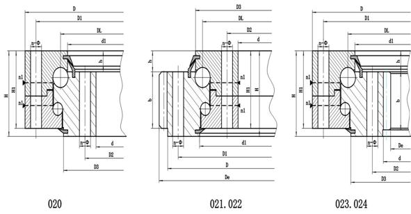
Double-row ball slewing bearing
CHARACTERISTIC OF STRUCTURE£¬PERFORMANCE AND APPLICATION
The Double-Row Ball Slewing Ring has three seat-rings. Steel Balls and Spacers may be poured directly into upper and nether orbits. Two rows of upper and nether Steel Balls of different diameters can be assembled according to Undertaking Power situation. The kind of open-pattern-assembly is very convenience. The load-angles of both upper and nether circular orbits are 90¡ã, which enable it to undertake very large Axial Force and Tipping moment. When the Radial Force is more than 0.1 multiple of Axial Force, the orbit need to be redesigned. As the axial and radial size of this kind of slewing ring are rather big, and the structure is firm, it is especially suitable for Tower Cranes of over-medium diameter, Truck Cranes, Loading and Unloading Machines, and so on.
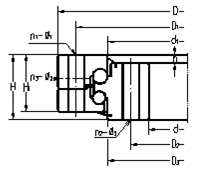
Double row thrust angular contact ball slewing bearing
| Model | Dimensions | Installation dimensions | ||
|
D1 D2 mm |
n1 n2 |
§¶1 §¶2 mm |
||
| Non-gear type | ||||
| JY020.12.563 | 600 460 70 | 580 482 | 45 46 | 9.3 9.3 |
| 5787/1916G2 | 2320 1916 150 | 2245 1980 | 42 42 | 34 34 |
| External gear type | ||||
|
6787/820G 6787/1600G 6788/1600G 6789/3405G |
1150 820 125 2000 1600 175 2000 1600 175 3638 3405 185 |
1100 880 1920 1675 1920 1675 3700 3465 |
14/4 8 10 20 24 24 48 48 |
25/22 32 38 38 32 32 35 35 |
| Internal gear type | ||||
|
7787/1310G 7787/2728K |
1600 1310 135 3100 2728 210 |
1550 1365 3040 2780 |
32 32 36 36 |
26 26 25 26 |
|
Designations (non- gear) |
Boundary dimensions | Bolt hole diameter | Structure dimensions | Mass | ||||||||||||||||||
| D | d | H | D1 | D2 | n | §æ | M | n1 | d1 | D3 | H1 | h | m | Z | X | K | ||||||
| mm | mm | mm | mm | mm | mm | mm | mm | mm | mm | mm | KN | KN | kg | |||||||||
| 020.30.900.** | 1042 | 758 | 124 | 998 | 802 | 30 | 22 | 20 | 6 | 871 | 877 | 114 | 29 | 316 | ||||||||
| 020.30.1000.** | 1142 | 858 | 124 | 1098 | 902 | 36 | 22 | 20 | 6 | 971 | 977 | 114 | 29 | 349 | ||||||||
| 020.30.1120.** | 1262 | 978 | 124 | 1218 | 1022 | 36 | 22 | 20 | 6 | 1091 | 1097 | 114 | 29 | 394 | ||||||||
| 020.40.1250.** | 1426 | 1074 | 160 | 1374 | 1126 | 40 | 26 | 24 | 5 | 1214 | 1215 | 150 | 39 | 709 | ||||||||
| 020.40.1400.** | 1576 | 1224 | 160 | 1524 | 1272 | 40 | 26 | 24 | 5 | 1364 | 1365 | 150 | 39 | 787 | ||||||||
| 020.40.1600.** | 1776 | 1424 | 160 | 1724 | 1476 | 45 | 26 | 24 | 5 | 1564 | 1565 | 150 | 39 | 899 | ||||||||
| 020.40.1800.** | 1976 | 1624 | 160 | 1924 | 1676 | 45 | 26 | 24 | 5 | 1764 | 1765 | 150 | 39 | 1018 | ||||||||
| 020.50.2000.** | 2215 | 1785 | 190 | 2149 | 1851 | 48 | 33 | 30 | 8 | 1962 | 1965 | 178 | 47 | 1586 | ||||||||
| 020.50.2240.** | 2455 | 2025 | 190 | 2389 | 2091 | 48 | 33 | 30 | 8 | 2202 | 2206 | 178 | 47 | 1789 | ||||||||
| 020.50.2500.** | 2715 | 2285 | 190 | 2649 | 2351 | 56 | 33 | 30 | 8 | 2462 | 2465 | 178 | 47 | 1990 | ||||||||
| 020.50.2800.** | 3015 | 2585 | 190 | 2949 | 2651 | 56 | 33 | 30 | 8 | 2762 | 2765 | 178 | 47 | 2243 | ||||||||
| 020.60.3150.** | 3428 | 2872 | 226 | 3338 | 2962 | 56 | 45 | 42 | 8 | 3102 | 3104 | 214 | 56 | 3762 | ||||||||
| 020.60.3550.** | 3828 | 3272 | 226 | 3738 | 3362 | 56 | 45 | 42 | 8 | 3502 | 3504 | 214 | 56 | 4272 | ||||||||
| 020.60.4000.** | 4278 | 3722 | 226 | 4188 | 3812 | 60 | 45 | 42 | 10 | 3952 | 3954 | 214 | 56 | 4828 | ||||||||
| 020.60.4500.** | 4778 | 4222 | 226 | 4688 | 4312 | 60 | 45 | 42 | 10 | 4452 | 4454 | 214 | 56 | 5465 | ||||||||
| Article3record page:1/3 page:1record 1 [ 2 ][ 3 ] > |